Retro Pi Radio

by Tom Sparrow

Back in 2016 Medway Makers were the first place winners in our class at the Pi Wars robotic competition at Cambridge University. Part of Medway Makers prizes for winning at PiWars was a Raspberry Pi audio amplifier hat and this device was the perfect opportunity to bring an old retro ‘Hacker’ (Yes, it really is called that)  radio up to date and into the 21st century.

DSC_0029

The radio was taken apart and I everything inside the radio that was no longer going to be used was discarded. Then, a Raspberry Pi with the amplifier hat was added inside and I soldered the output to the original radio’s speaker.

DSC_0027

There are several software choices to use for your internet radio, and I decided to use Volume IO. This was flashed to the micro SD card of the Raspberry pi. Volume IO has a nice, easy to use web interface, the official app works well, and it’s easy to add your own music collection via a USB stick.

volumio


BBC Master 128 Restoration

Over the Christmas period, Mike was lucky enough to be gifted a BBC Master 128 along with a 5.25″ disc drive, a load of cables and a few games on tape. The poor BBC Master had been sat in a garage for approximately 10 years with a load of wood on top of it, gathering dust and becoming a home for spiders and beetles. Obviously, the computer was in need of some essential TLC before it could be put into use.

First, the BBC Master needed a good strip down and a clean. The PSU, motherboard and keyboard were all removed from the case. The case was full of dust, dead spiders and beetles and was very dirty. The keyboard was absolutely filthy and was first to be stripped down and cleaned. All of the keys were taken off and given a good wash in soapy water, the chassis was cleaned up as best as possible with some brushes and cotton buds and then the whole thing reassembled. The final result was a massive improvement.

Next, the two sides of the clamshell case were washed in the shower with hot soapy water to remove all of the dirt. The case is very heavily yellowed with age and a future project for the summer is to carry out the retrobright process on the case to bring it back to white again. Next, the motherboard was given a vacuum and the board a brush and wipe down.

img_20200101_185507

Next, the PSU needed some work. There are three capacitors in the BBC Power Supplies that are notorious for drying out over the 30+ years it has been since they were manufactured and when they get hot they emit smoke and die. Mike purchased a capacitor replacement kit from eBay and the three offending items were replaced. The existing capacitors did look like they were in good shape, but it was better to be safe than sorry. 

Finally, the battery pack needed replacing. The pack had the original Duracell batteries from the 1980’s and they had leaked all over the place. The pack was thrown away and replaced with a newly made pack using a 3 AA battery holder, diode and resistor.

Next, it was time to install the TurboSPI ROM chip and the SD Card adapter that was purchased at the same time as the capacitor kit. This would allow instant loading of games and other programs from the SD card and allows up to 512 disc images to be loaded onto the card. This was a simple case of pushing the ROM into an empty slot and pushing the SD card PCB into the user port on the underside of the computer.

Now everything was setup and ready to go, it was time to turn the computer on and hope it all worked. Voila! Everything worked fine.

img_20200102_183625-1

After a few configuration commands were typed in to reset the configuration after it being turned off for so long and the battery pack no longer providing backup power, the Turbo MMC system was available and the contents of the SD Card could be accessed.

img_20200108_200639

On the SD Card that came with the system are well over 1000 games that can be accessed from a menu system on Disc 0. These only take up around 50% of the available 512 disc slots leaving plenty empty to load your own games or to save your own programs to. All of the classics were present.

The BBC Master 128 proved to be a big hit at the next Medway Maker social meetup on Sunday 5th January with several members getting very competitive at Pacmanand a few other games.

There are a few more upgrades on the horizon with a Raspberry Pi co-processor on its way and a ROM for a BBC Master 128 specific MAMMFS file system so that Elite can be played properly.

You can see the BBC Master in use in this timelapse movie below of the last Medway Makers session on Sunday 5th January 2020.


Magnetic Encoder Tests

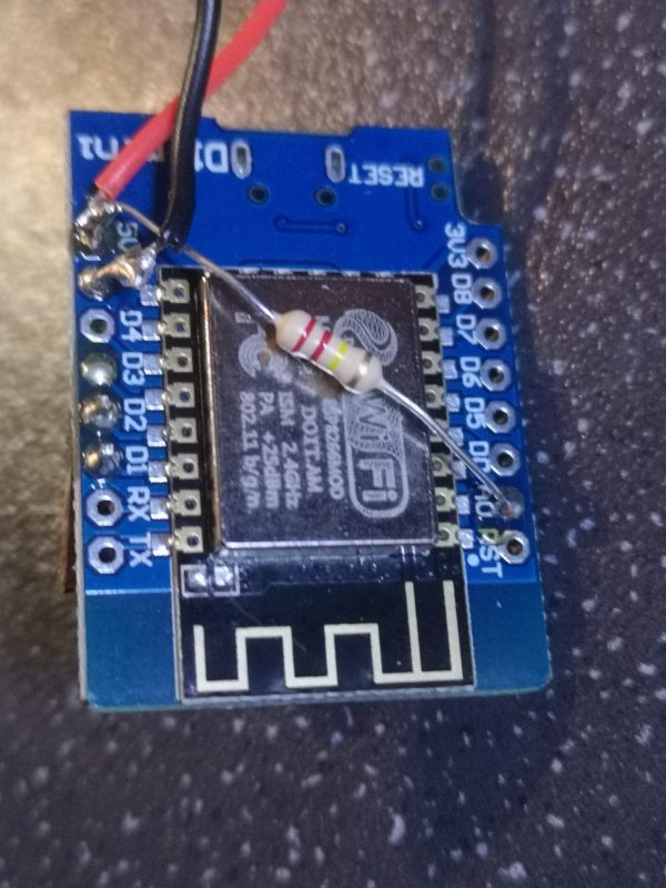
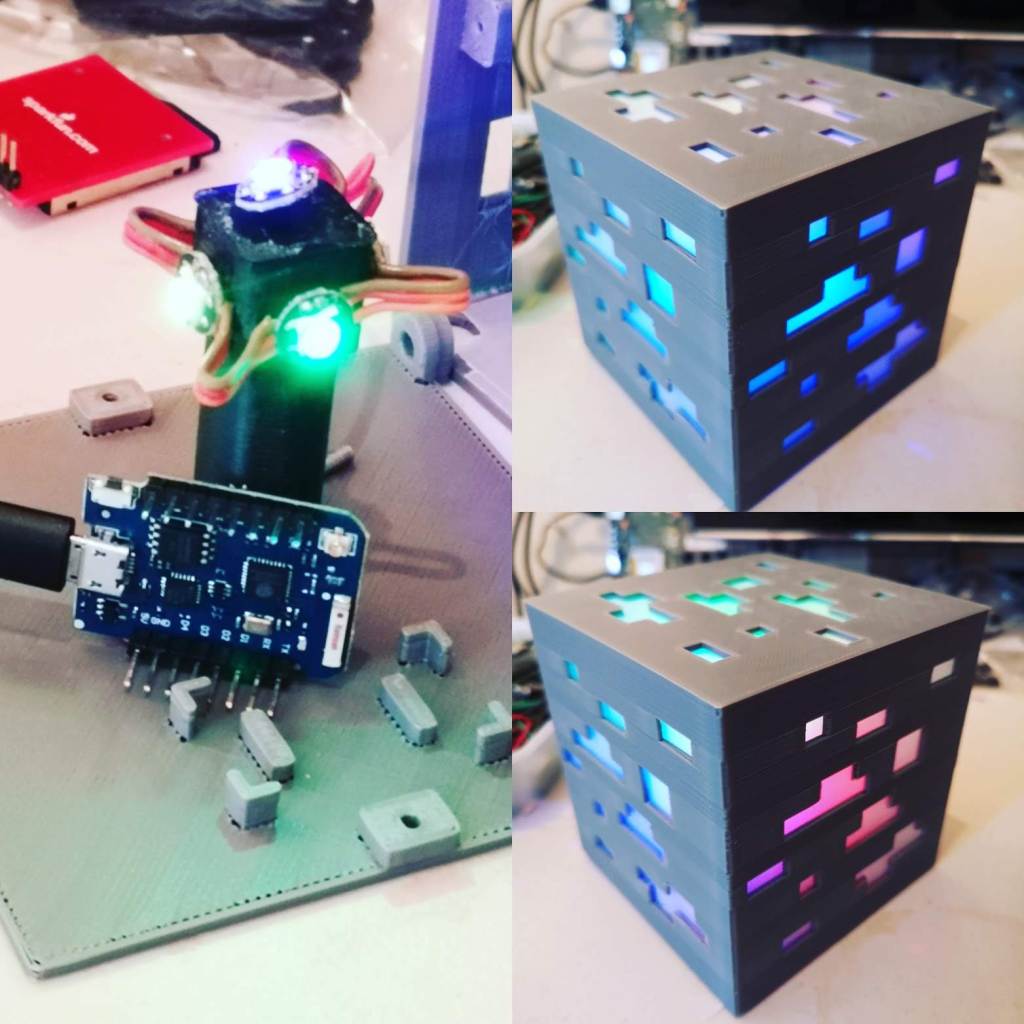
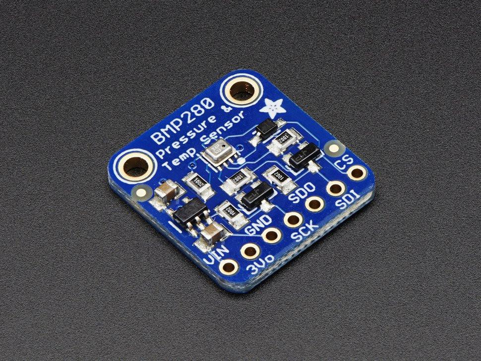
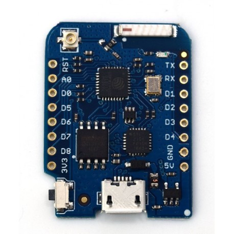
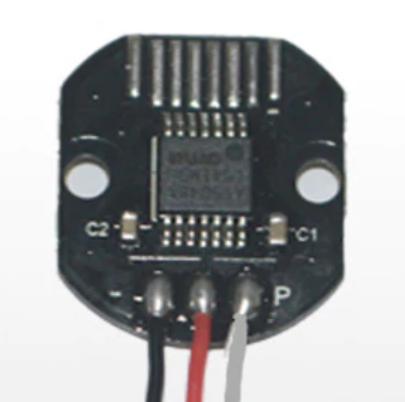
I recently purchased some magnetic encoders to use in an upcoming project and hooked them up to a Wemos D1 Mini to try and do some basic testing. The specific magnetic encoder is the AS5048. Three wires were soldered to the PWM output pins only as this is a lot easier than soldering wires to the very slim SPI tabs. As long as the PWM output works as expected then there will be no need for using the SPI interface.

AS5048 Magnetic Encoder

To read the PWM output I uploaded a simple PWM read sketch to the Wemos and took a look at the output on a serial monitor. It was then that the output was seen to be not as expected.

The expected output was a series of numbers ranging from 0 to some other higher number as the magnet was rotated above the IC. However, the numbers seemed random and only seemed to match the expected output when the magnet was revolved around an axis that was on the edge of the magnet and not the centre. It was then that I realised that I was using the wrong kind of magnet. The standard neodymium magnets that you can buy for attaching things to your fridge etc. are magnetised with their poles on the opposite faces. Magnetic encoders are designed to work with diametrically magnetised magnets, i.e. those that have the north and south poles on the opposite edges of the magnet with a split down the middle of the face.

So some magnets were purchased from Amazon that were clearly marked as diametrically magnetised and even had in the description:

” Each magnet’s north and south pole are on opposite curved sides.
Unusually, diametrically magnetised magnets are not designed to hold the maximum possible weight for the size of the magnet but instead are used to provide rotational movement.
A diametrically magnetised magnet is magnetised across its diameter so that the north pole in on one curved side and the south pole is on the opposite curved side.
Diametrically magnetised magnets are used on the end of shafts to provide drive. “

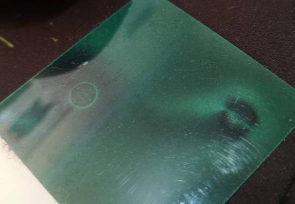
Despite this, when the magnets arrived and were tested the output was exactly the same as a standard magnet. It was obvious to me that these were not diametrically magnetised at all. So I purchased a very small square of magnetic field view paper (really cool stuff). When it arrived I put a standard magnet and what was supposed to be the diametrically magnetised magnet under the paper. The result was this:

Not diametrically magnetised magnets

The standard magnet is on the left and the ‘diametrically magnetised’ magnet is on the right. As you can see clearly, they are identical. So I initiated a return and refund on Amazon immediately and reported the seller for selling magnets that were described as diametrically magnetised when they were not. Of course, Amazon has done f**k all about it and they are still being sold.

I then found https://www.first4magnets.com/ and spoke to a customer representative. They assured me that their magnets described as ‘diametrically magnetised’ were exactly that, so I ordered a small pack of 10 x 6mm disc magnets. When they arrived, I again tested them with the magnetic field view paper and voila!

Left – Standard magnet. Right – Diametrically magnetised magnet.

As you can see the diametrically magnetised magnet on the right has a coffee bean shape with the north and south poles emanating from the left and right sides of the disc rather than top/bottom faces. This is exactly what I wanted.

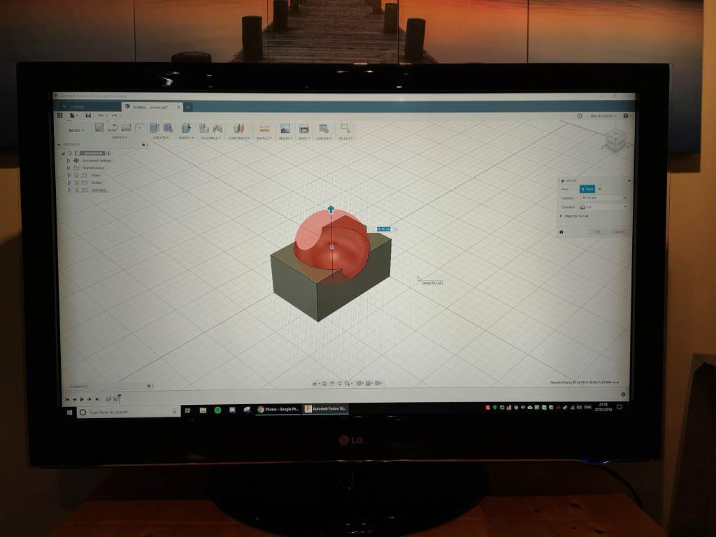
Tests with the AS5048 show a more expected output, with the only difficulty being in keeping the magnet central to the IC when holding it by hand. However, the output is going from zero up to about 900ish and then going back to zero. This is more in line with what I was expecting. So next I am going to 3D print some kind of jig to keep the magnet dead centre on the IC and the correct distance from it, so it can be tested properly. I can then use this as a test-bed for the upcoming project I intend on using these for (watch this space).

Upgrading to a Pi 4 with SSD

Mike has decided to upgrade his InfluxDb and Grafana server from the Pi 3B+ to a new Pi 4 with 4Gb of RAM. To speed things up even further, he purchased an M2 NVMe SSD card to boot the OS from and make the speedy Pi 4 even faster.

WD Blue SN500 M2 SSD

The SSD is a WD Blue SN500 M2 NVMe SSD which has a 250Gb capacity. The drive is contained inside a USB 3 enclosure. The Pi 4 was flashed with a brand new copy of Raspbian Buster and then the latest versions of InfluxDb and Grafana were installed

Mike used the instructions from on the ‘Toms Hardware’ website which can be found HERE.

The SSD inside the USB 3.0 enclosure

The Pi 4 with the SSD is now considerably faster than the old Pi 3. Grafana dashboards load faster and in particular, choosing data ranges in Grafana displays the data noticeably quicker than previously. The extra 3Gb’s of Ram should also ensure that the Pi does not start grinding to a halt as the database gets larger.

To keep the Pi 4 cool it is being moved soon to a new Pimoroni PiBo case with the fan shim. This will then be stuck to the back of a monitor in portrait format to display the Grafana dashboards.

4Gb Pi 4 with 250Gb SSD in a USB 3.0 enclosure

If you want a much faster Pi with plenty of storage space, an external M2 SSD is recommended with a Pi 4.

ESP8266 Sensor Node

ESP8266 temperature & humidity sensor node

Mike has recently been adding some more sensors to his sensor network around the house. To add to the Weather Station sensors that are out in the garden, plus the Environmental Monitoring Station sensors and CO2 sensor node, a BME280 temperature and humidity sensor node has been added to the network.

Data from this sensor node is being transmitted back to Mike’s InfluxDB database on a Raspberry Pi. The new sensor node is currently in the bathroom with similar nodes being added in future and dotted around the house.

This particular sensor node is in a ‘dead bug’ style with all of the components soldered directly to each other, rather than using a breadboard or PCB. For such a simple circuit this is ideal and makes the whole thing compact.

Voltage divider resistor to monitor battery voltage

A 220K ohm resistor was soldered between the 5v input pin and analog pin A0 to allow for the battery voltage to be monitored. The node takes temperature, humidity and voltage readings every 20 minutes, transmits this to the InfluxDB database and then goes to sleep.

The BME280 sensor

All of the data, once stored on the Raspberry Pi is displayed sing Grafana’s beautiful dashboard graphs and gauges as below.

Grafana dashboard

The code for this project can be found on Mike’s Github HERE.

Making an Arduino based Simon Game

So we decided at |Medway Makers to do a little collaborative project and to do a workshop on building and coding a ‘Simon’ game.

This was mainly born out of a complaint from Tom that he had bought a mini Simon Game and that it was not the same game he remembered as a kid. So, we decided let’s build our own.

Arduino based Simon

We used an Arduino Nano, 4 large buttons with clear caps and 4 LEDs, plus piezo buzzer for the tunes. The circuit is really simple with pull down resistors on each button and current limiting resistors on each LED.

The code creates a random note selected from 4 possible notes and adds it to an array. The note is then played and the corresponding LED is lit. The player then has to press the appropriate button to match the note. If he succeeds, another random note is chosen, added to the array and the tune played so far. This is repeated for as long as the player is able to remember the sequence. The speed of the tune being played back is also increased slightly in each round until eventually it will become impossible

The code plus the circuit for this project can be found on Mike’s Github HERE.

Check out this video for the game in action.

Meetup and Neopixel Workshop – Sunday 28th July

Our next meetup is Sunday 28th July. I shall be running a small workshop on how to use Neopixels and how to write code to control them using the Arduino or Raspberry Pi.

We are a group of creative technologists that meet every 2-3 weeks on a Sunday between 11am and 5pm for a general social and making session. Everyone is welcome to bring something down and work on it and share and get involved with members projects or to simply see what we are up to. There is no fee to join or attend any session.

Medway Makers is a place for creative people to get together to make things, learn new skills, make new friends, socialise, talk about ideas, watch people build things and generally be creative.

We have workshops in building cool things with Arduino and Raspberry Pi, learn about electronics, how to code for beginners, writing computer games for an Arduboy or other devices, designing in 3D CAD programs, 3D Printing, how to use a Raspberry Pi and so on. We have also done woodworking, making terrariums, painting and other creative activities.

Complete beginners welcome. No prior knowledge, skills or equipment is needed. Just bring yourself and your curious mind. We can provide laptops and equipment if you don’t have your own.

The best thing about all of this : IT’S FREE !!!

Medway Makers does not and shall not discriminate on the basis of race, color, religion (creed), gender, gender expression, age, national origin (ancestry), disability, marital status, sexual orientation, or military status, in any of its activities or posts. We are committed to providing an inclusive and welcoming environment for all our members and expect all members to do the same. Any person found to be acting in a discriminatory manner will be ejected from the group.

Note that meetings are held in either the Medway area or in Gravesend/Chalk area. We do not have a dedicated space (yet) and so are meeting at members houses until we do.

Beautiful Custom Wooden Knife Handle Build

Beautiful custom wooden knife handle by Tom Sparrow

In a departure from our usual electronics based builds, Tom Sparrow has been experimenting with making some beautiful wooden handles for gardening knives. Tom says…..


I started by drawing some designs on paper first, then making a model of the knife out of wood as I wanted to make sure it was comfortable for me before starting the real thing. A bit of filing was needed here and there before feeling nice in my hand.

Knife designs on paper

I have been away from soldering and back to primitive making by making a knife for gardening and odd jobs.

Making a jig for the handle

I bought a large knife blank, then drew the shape of my design onto the steel. I then cut it slightly oversized with an angle grinder and finished the shape with a course file.

Transfer the design to the steel blank

Onto the handle! There are some really pretty materials for knife handles, as this was the first attempt I opted for olive wood, which was easy to use and has a nice distinctive grain.

Shaping and sanding

It was just a case of putting it all together now and making it look tidier, so I cut 2 pieces of the wood for the handle and glued them on with 2 part epoxy.

Beautiful custom knife build by Tom Sparrow

After 30 hours drying time the excess wood just had to be sanded to the shape of the knife tang, then the long process of sanding the wood and blade with finer and finer sandpaper and finally finishing the wood off with linseed oil.

A work of art

In the future, I would like to try to make a knife from scratch and heat treat it myself, and maybe try something a bit more interesting for the handle.

A custom holder to go with the knife

Giant RGB LED Display + ESP8266

Giant RGB LED display

I’ve been working on a giant RGB LED Display recently. The video above shows you some test animations running through the display.

Currently the display is 25 x 17 in size and will be expanded to be 25 x 25 LEDs in total.

The display is made up of WS2812 Neopixel strips powered by a 20A 5v PSU. Animations are generated by Jinx! LED control software and then sent over WiFi using the tmp2.net protocol to an ESP8266 connected to the RGB strips.

The LEDs will have a grid overlaid on top of them to isolate each LED and finally a thin white acrylic layer will go on top to diffuse them. Keep an eye on this project for further updates.

Environmental Monitoring Station + ESP32 + Raspberry Pi + InfluxDB + Grafana

So, over the last few months I have been curious as to the levels of pollution during my commute to work. I have to drive from the countryside of Kent into the Isle of Dogs, London, via the Blackwall Tunnel and at part of that journey I can literally taste the fumes from the other cars. I thought it would be interesting to try and see what the levels of particulates are plus some other air pollutants and so set of on a journey to build a sensor station with some relevant sensors for this task.

After speaking to Oly at Maidstone Hackspace, who had built something similar, I decided on the SPS30 particulate sensor and an MH-Z19 CO₂ sensor. I also added uBlox NEO 6M GPS module so that I could obtain accurate time plus the location of the device when in mobile mode. I also added an HTU21D temperature and humidity sensor. The entire thing currently looks like the prototype below.

Environmental Monitoring Station

Bottom middle is the microcontroller. I have used an ESP32, mainly as it is an ESP based device with plenty of GPIO pins. I needed a few for the various devices plus room for additional sensors in the future.

Right of that is the uBlox NEO 6M GPS module. Currently I am only extracting time and date from it but will also be capturing longitude and latitude data so I can record where the device was whilst in mobile mode.

Above the GPS modile is a HUT21D temperature and humidity sensor.

Above the ESP32 is a small golden box. This is the MH-Z19 CO₂ sensor. Left of that is a 2.2″ TFT display showing the various bits of data from the sensors. You can see I am displaying the PM2.5 and PM10.0 values as well as the CO₂ reading, temperature and humidity.

Above the display is the SPS30 particulate sensor. This was the most expensive sensor in the setup at approx £30 each. However, it comes highly rated and has excellent reviews. Above the SPS30 is a breadboard PSU as the ESP32 does not have enough juice to power all of the devices via USB.

I will be adding an SD Card reader/writer module soon to enable me to log the data to SD Card including the location of the device when on the move. At first, all of the data I was sending up to ThingSpeak to record and display it. This was fine to start with but I soon became frustrated with the very limited graphing and display options with ThingSpeak. I wanted the ability to be able to zoom in and out of graphs, which ThingSpeak does not offer. I then came across the open-source Grafana project which allows you to display your data in beautiful ways and has the option to annotate certain parts of the graph, change what date and time range to display on the graph quickly and easily as well as zoom in and out on whatever area you want at any time.

As I had a few spare Raspberry Pi’s lying around I decided to go down the route of self-hosting my own data and graphs. So I took a Pi, installed InfluxDB as my database to store the sensor data and also Grafana to display all of the readings. All of the above was pretty easy to set-up. There are plenty of tutorials online to assist you with this.

Grafana

I have to say I am very pleased with the results so far. As you can see above the Grafana dashboard looks amazing. You have plenty of options with regard to how the data is displayed and what colours to use, etc. It has been a very interesting experience to watch the levels of CO₂ go up and down in rooms that are occupied or not, or have ventilation or not. I have to admit I am more inclined to keep windows open since seeing the CO₂ readings go above 1000ppm on occasion. It is also seeing the levels of particulates go up into what is considered unhealthy ranges just by doing things like cooking. You can also tell when people are getting out of bed, moving around the house, etc. by the particulate levels as the settled dust gets kicked up into the air again. The whole project has been a real eye opener.

I have a whole bunch of the MQ sensors and intend on adding a few onto the sensor station, particularly those relevant to car fumes so I can use the device in mobile mode and take it in the car on a daily commute.

Overall this has been a very satisfying project and a real eye opener as I was totally unaware of the levels of pollution just inside my own home. I would recommend you, the reader, to also build one of these as you will be surprised at what you find. Give me a shout if you have any questions or need some help with your own project.

Air Quality Monitoring Station

I’ve started a new project recently to build an air quality monitoring station. This really came about after me being curious as to how bad the air quality was during my daily commute into London. There are parts of that commute where I can literally taste the car fumes and so was curious exactly how bad it really was. Also, I watched a video recently about how high CO2 levels affect your cognitive performance and that got me very curious as to what the levels of CO2 were, both at home and in my work office. So, I decided to build a portable air quality monitoring station to sense and record the levels of both particulates, CO and CO2, with more sensors to be added at a later date.

So, the micro-controller I am using for this project is a NodeMCU Amica which is an ESP8266 based device. The advantage of this is a fast processor (up to 160MHz) lots of memory (4Mb) and plenty of pins broken out to add peripherals to. I am currently using a small ILI9341 based TFT colour display and have an Sensirion SPS30 particulate sensor attached to display the size and concentration of particles. I also have an MQ9 Carbon Monoxide sensor and a MH-Z19 Carbon Dioxide sensor. Both have yet to be attached.

In the image above you can see the current output on the display. Top left and right I am showing the number of particles of sizes 2.5 microns or smaller and 10 microns or smaller respectively per metre cubed. The bottom shows the concentration of these sized particles per cm cubed. I am using a NEO-6M GPS module to provide the data and time for logging purposes. I will also be using this to log the location for when the device is being used during travel or in different locations.

Prototype for the air quality monitoring station

The code currently keeps a running average of the totals per minute, per hour and per 24 hours. These will be used to display the Air Quality Index (according to Defra).

Later additions to this project will be to add the CO and CO2 sensors, to record the data onto an SD Card and to also transmit the data to somewhere it can be viewed online. I may use the Adafruit MQTT service for this. I have not decided fully yet. I may also add in further sensors at a later date to make it into a full environmental monitoring station and couple the data from this device with that being received from my external weather station.

If you are interested in seeing this device in action or would like to learn how to build your own, then pop along to a Medway Makers meetup to see it for yourself. Further updates to this project will be posted as further progress is made.

Minecraft Ore Lamp

So we started a little fun project recently to make some RGB Mood Lamps. We chose a Minecraft Ore block as the basis for the lamp itself. I found the STL files to 3D Print the block on Thingiverse. A few were printed out using black filament and several were done in matt grey. The original lamps had a holder on the base designed to fit an Arduino Micro Pro. As this is a kind of Arduino I never use I redesigned a new base that would hold a Wemos D1 Mini. The Wemos has an ESP8266 module and so gives the lamp WiFi capability to enable remote control.

Minecraft Ore Lamp using a Wemos D1 Mini

In the centre of the lamp are 5 RGB neopixels to allow any chosen colour on all 5 visible sides. The photo above shows some nice colour gradients between the sides.

After assembling the lamps I then wrote some code to make the lamps change colours, do some patterns and some modes such as ‘Police Mode’ where it flashes blue and red like a Police car.

I then added some further code to enable the lamp to be controlled from a mobile phone using the Android Blynk app. The app allows you to choose any colour you want, to turn the lamp on and off and to choose Police Mode. Further modes will be added as and when I get around to coding them.

Blynk app for the Minecraft Ore Lamp

A video of the lamp in action can be seen below.

I shall be posting up the code on my GitHub once complete.

Website Built with WordPress.com.

Up ↑