Controlling 2 LEDs with 1 pin

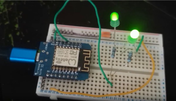
Not many people know that it is possible to control 2 LEDs individually with just a single digital output pin. See the video below for proof. These 2 LEDs are both connected to the same pin, digital pin D5 on a Wemos D1 mini.

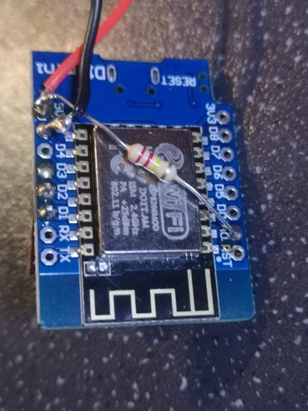
How is this magic possible? Take a look at the circuit diagram. As you can see we have both of the LEDs connected to the same digital pin. However, one LED has its cathode (negative leg) connected to ground and the other one is connected to 5v (or 3v on a Wemos D1).

To light up LED 1, make the digital pin an output and make the pin HIGH. Electricity will flow from the digital pin to ground, lighting up LED 1. To light up LED 2, make the digital pin go LOW. Now the electricity will flow from the 5v (0r 3,3v) pin to ground via the digital pin that has been pulled low.

To turn both LEDs off, make the digital pin an INPUT, which will prevent the voltage from going anywhere and both LEDs now turn off.

So, how do you light up both LEDs? Well, it is not possible. However, you can trick your eye into seeing they are both on by turning each LED on in quick succession very very fast.

Take a look at the entire code below and you will see how to turn both LEDs on at the same time in the do…while loop.

unsigned long counter;

void setup() {
    pinMode(D5, OUTPUT);
}

void loop() {
    // Turn LED A on B off
    pinMode(D5, OUTPUT);
    digitalWrite(D5, HIGH);
    delay(1000);

    // Turn LED B on A off
    digitalWrite(D5, LOW);
    delay(1000);

    // Turn LED A and B on (very fast)
    counter = millis();
    do
    {

        digitalWrite(D5, HIGH);
        digitalWrite(D5, LOW);
    } while ((millis() - counter) < 1000);

    // Turn LED A and B off
    pinMode(D5, INPUT);
    delay(1000);
}

The only disadvantage to this is when both LEDs are apparently on they re slightly dimmer then when on individually. However, for the sake of saving 50% of he number of pins this is a small trade-off.

ESP8266 Sensor Node

ESP8266 temperature & humidity sensor node

Mike has recently been adding some more sensors to his sensor network around the house. To add to the Weather Station sensors that are out in the garden, plus the Environmental Monitoring Station sensors and CO2 sensor node, a BME280 temperature and humidity sensor node has been added to the network.

Data from this sensor node is being transmitted back to Mike’s InfluxDB database on a Raspberry Pi. The new sensor node is currently in the bathroom with similar nodes being added in future and dotted around the house.

This particular sensor node is in a ‘dead bug’ style with all of the components soldered directly to each other, rather than using a breadboard or PCB. For such a simple circuit this is ideal and makes the whole thing compact.

Voltage divider resistor to monitor battery voltage

A 220K ohm resistor was soldered between the 5v input pin and analog pin A0 to allow for the battery voltage to be monitored. The node takes temperature, humidity and voltage readings every 20 minutes, transmits this to the InfluxDB database and then goes to sleep.

The BME280 sensor

All of the data, once stored on the Raspberry Pi is displayed sing Grafana’s beautiful dashboard graphs and gauges as below.

Grafana dashboard

The code for this project can be found on Mike’s Github HERE.

Air Quality Monitoring Station

I’ve started a new project recently to build an air quality monitoring station. This really came about after me being curious as to how bad the air quality was during my daily commute into London. There are parts of that commute where I can literally taste the car fumes and so was curious exactly how bad it really was. Also, I watched a video recently about how high CO2 levels affect your cognitive performance and that got me very curious as to what the levels of CO2 were, both at home and in my work office. So, I decided to build a portable air quality monitoring station to sense and record the levels of both particulates, CO and CO2, with more sensors to be added at a later date.

So, the micro-controller I am using for this project is a NodeMCU Amica which is an ESP8266 based device. The advantage of this is a fast processor (up to 160MHz) lots of memory (4Mb) and plenty of pins broken out to add peripherals to. I am currently using a small ILI9341 based TFT colour display and have an Sensirion SPS30 particulate sensor attached to display the size and concentration of particles. I also have an MQ9 Carbon Monoxide sensor and a MH-Z19 Carbon Dioxide sensor. Both have yet to be attached.

In the image above you can see the current output on the display. Top left and right I am showing the number of particles of sizes 2.5 microns or smaller and 10 microns or smaller respectively per metre cubed. The bottom shows the concentration of these sized particles per cm cubed. I am using a NEO-6M GPS module to provide the data and time for logging purposes. I will also be using this to log the location for when the device is being used during travel or in different locations.

Prototype for the air quality monitoring station

The code currently keeps a running average of the totals per minute, per hour and per 24 hours. These will be used to display the Air Quality Index (according to Defra).

Later additions to this project will be to add the CO and CO2 sensors, to record the data onto an SD Card and to also transmit the data to somewhere it can be viewed online. I may use the Adafruit MQTT service for this. I have not decided fully yet. I may also add in further sensors at a later date to make it into a full environmental monitoring station and couple the data from this device with that being received from my external weather station.

If you are interested in seeing this device in action or would like to learn how to build your own, then pop along to a Medway Makers meetup to see it for yourself. Further updates to this project will be posted as further progress is made.

Minecraft Ore Lamp

So we started a little fun project recently to make some RGB Mood Lamps. We chose a Minecraft Ore block as the basis for the lamp itself. I found the STL files to 3D Print the block on Thingiverse. A few were printed out using black filament and several were done in matt grey. The original lamps had a holder on the base designed to fit an Arduino Micro Pro. As this is a kind of Arduino I never use I redesigned a new base that would hold a Wemos D1 Mini. The Wemos has an ESP8266 module and so gives the lamp WiFi capability to enable remote control.

Minecraft Ore Lamp using a Wemos D1 Mini

In the centre of the lamp are 5 RGB neopixels to allow any chosen colour on all 5 visible sides. The photo above shows some nice colour gradients between the sides.

After assembling the lamps I then wrote some code to make the lamps change colours, do some patterns and some modes such as ‘Police Mode’ where it flashes blue and red like a Police car.

I then added some further code to enable the lamp to be controlled from a mobile phone using the Android Blynk app. The app allows you to choose any colour you want, to turn the lamp on and off and to choose Police Mode. Further modes will be added as and when I get around to coding them.

Blynk app for the Minecraft Ore Lamp

A video of the lamp in action can be seen below.

I shall be posting up the code on my GitHub once complete.

Website Built with WordPress.com.

Up ↑