by Declan Heard
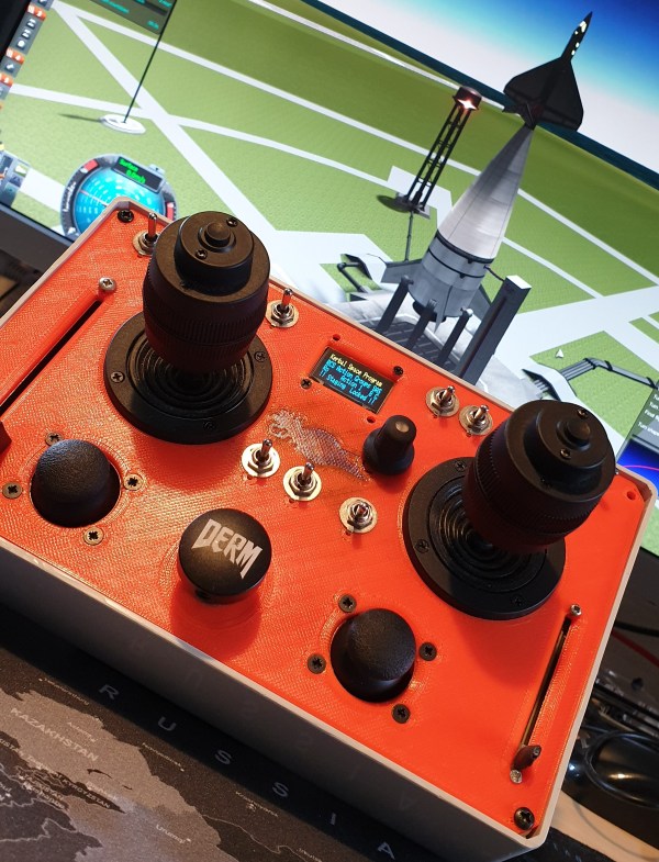
How about a custom 10 Axis Controller?
Kerbal Space Program is a brilliant game/Space Flight Simulator, it teaches the basics of rocket science, and aerodynamics, and lets you test out crazy contraptions that only exist in science fiction and never before realised concepts.
The scope for this project was to replace the typical keyboard game controls, with a far more interactive, intuitive and fun Analogue Stick control layout. I wanted to be able to assign different controls depending on whether a Rocket is being flown to orbit, a Spaceplane was lining up on final approach to a runway, or a Rover was being driven across the surface of The Mun.
The controller runs off an Arduino Mega 2560 and uses the Kerbal SimPit Mod installed in the Game Data folder of Kerbal Space Program. The ready-made Arduino library, Kerbal SimPit is available from the Arduino Library Manager, and this handles all the communication between the controller and the game.
Functions:
As well as the typical flight controls, Pitch, Yaw, and Roll, the controller also handles translation controls, i.e. movement in the X, Y and Z direction when the Reaction Control Thrusters (RCS) are enabled and Rover Wheel commands, Throttle and Steering when in Rover Mode.
To be able to control each of these parameters in unison, I used two 3 axis joysticks that would operate most of the main flight controls, and two 2 axis joysticks to cover rudders in plane mode and some of the RCS translation controls. This is way more options than is really needed, but it gives the pilot scope to adapt the controls to suit different vehicles and flying styles.
A simple slide pot enables fine control of the Main Engine Throttle, which makes precise landing burns easy and fun to pull off. No more need for parachutes, just make sure you have enough fuel to complete your suicide burn!
A large Staging button in the centre of the console takes the place of the spacebar. Press this button to go to space. Always make sure you check your staging before hitting the go button.
Once underway, its often prudent to lock the staging button until it is required again. A handy toggle switch is provided to lock the staging button, ensuring your rocket doesn’t break into different pieces at an inopportune moment.
The other switches let the pilot raise and lower the gear, apply brakes, toggle SAS (Stability) and RCS modes, or trigger any of 10 or 20 different custom actions depending on which other mods you have installed.
Of course, any Rocket is incomplete without some way of aborting the flight and saving the cosmonauts when everything is going wrong. In case of RUD, Rapid Unscheduled Disassembly, pressing and holding the Abort Switch prompts the pilot to press the stage button to engage Abort Mode.
Once Abort Mode is engaged, there is no turning back. If you have set it up your actions correctly, your crew capsule separates, the abort motors fire, and your crew is dragged, kicking and screaming away from any impending explosions, and..…are safe. You remembered to pack parachutes, right?
Operation:
On boot up, if the Arduino finds a config file saved to the CD card it applies the last saved settings, if it cannot find a file it boots with factory settings, and creates a config file to save settings into. It then runs a self-calibration to make sure all the joysticks are outputting zero.
The OLED screen displays various actions, like which SAS mode has been triggered, and the status of Brakes and the Gear. It also lets budding Astronauts change and save the different options for each of the flight modes, Rocket, Plane and Rover, run the calibration routine, and set the SD card to restore the factory config file on bootup.
Design:
The front panel was designed in Fusion 360, and 3D printed to fit an off the shelf Hammond, although this version was measured slightly inaccurately and required a small amount of filing to get some parts to fit.
The wiring was planned using DIY Layout Creator, I wanted every connection on header pins, allowing easy maintenance and future expansion or improvements. All the power, GND and Signal wire to and from the front panels, including pull up and pull-down resistors would be over two daughterboards.


Improvements:
Due to the limitations of the mod and the game functions, several of the switches for the SAS autopilot do not function as well as hoped and occasionally cause the game to crash when operated.
These controls are also assigned to the keyboard numpad, so a second controller could be used to handle these commands, as well as some other keyboard shortcuts the game relies on, like changing camera views and controlling the time warp functions. This could run on an Arduino Leonardo, which would show up as a keyboard or Joystick input to the computer.
I would really like to improve the front panel, possibly make it into a single PCB that can have the control labels silkscreened directly on. This could also save all of the offboard wiring, and a single ribbon cable used to connect the Arduino to the front panel.
For the source code for this project, see my GitHub repo @:
https://github.com/PanGalacticTech/Kerbal_Controller
Full instructional writeup due at some point.